Electron inelastic mean free path and mean inner potential of liquid water
- Abstract number
- 372
- Event
- Virtual Early Career European Microscopy Congress 2020
- Presentation Form
- Submitted Oral
- DOI
- 10.22443/rms.emc2020.372
- Corresponding Email
- [email protected]
- Session
- PST.1 - Phase Microscopy
- Authors
- Postdoc Murat Nulati Yesibolati (2), Senior Researcher Shima Kadkhodazadeh (2), Associate Professor Marco Beleggia (2), Ph.D. Simone Laganá (2), Ph.D. Hongyu Sun (2), Research scientist Shawn M. Kathmann (3), Professor emeritus Ole Hansen (2), Senior scientist Nestor J. Zaluzec (1), Associate Professor Kristian Mølhave (2)
- Affiliations
-
1. Argonne National Laboratory, Photon Sciences Division
2. DTU Nanolab, National Centre for Nano Fabrication and Characterization, Technical University of Denmark
3. Physical Sciences Division, Pacific Northwest National Laboratory
- Keywords
mean inner potential, mean free path, liquid water, electron holography,liquid phase transmission electron microscopy
- Abstract text
Liquid phase transmission electron microscopy (LPTEM) is emerging as a powerful method to investigate the evolution of materials’ morphology and chemistry in-situ in their native liquid environment down to atomic resolution [1,2]. Here we present studies of mean inner potential (MIP, V0) of liquid water [3], and electron inelastic mean free path ( lIMFP) in liquid water using an advanced nanochannel liquid cell [4] in TEM.
MIP of liquid water
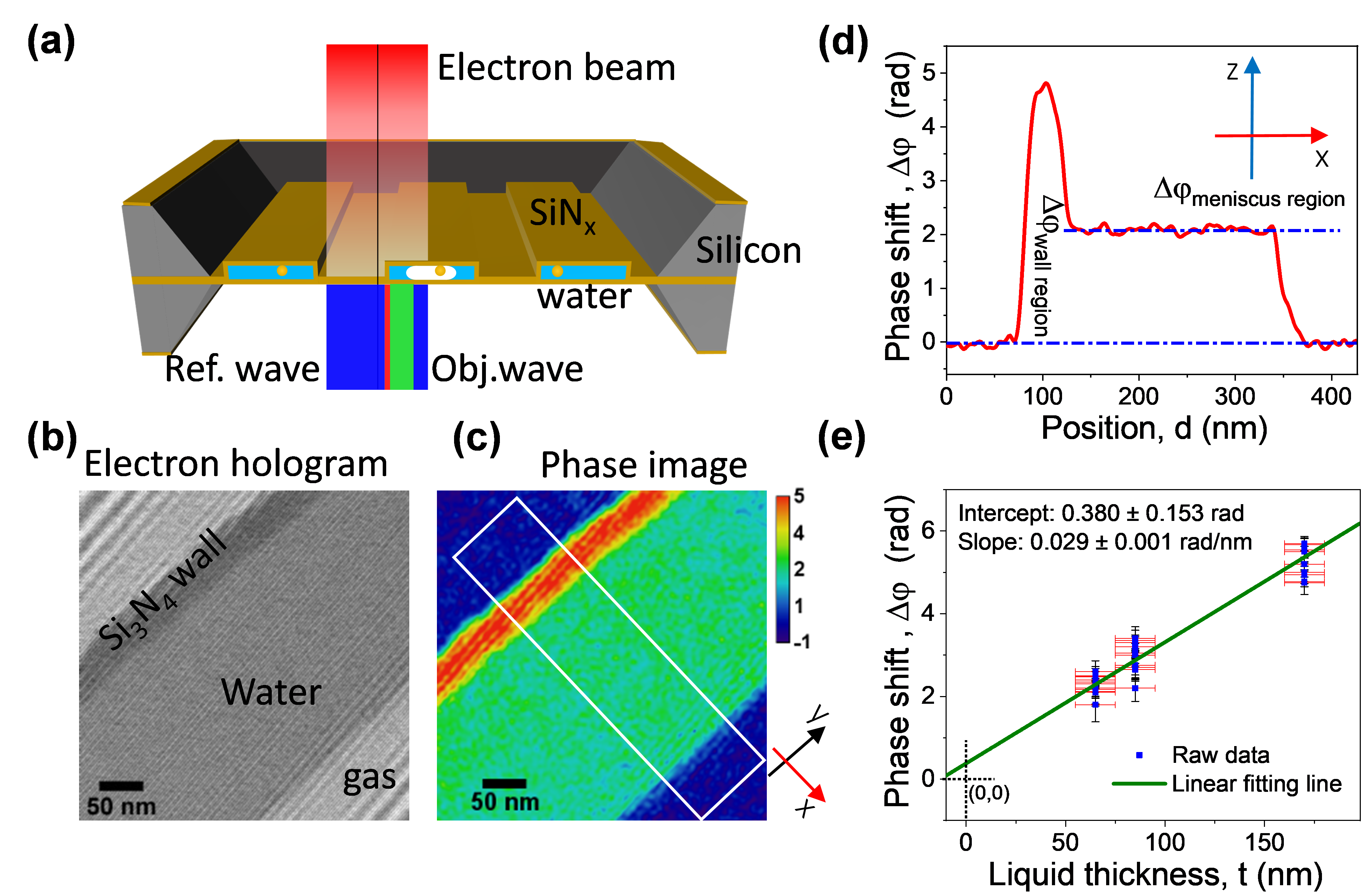
The unscattered electrons’ phase shift after passing through the sample carry information of the samples atomic constituents and potentials. Improving our experimental and theoretical knowledge of electric potentials at liquid-solid boundaries is essential to achieve a deeper understanding of the driving forces behind interfacial processes. Electron holography [5] has proved successful in probing solid-solid interfaces, but requires knowledge of the materials’ mean inner potential (MIP, V0), which is a fundamental bulk material property. Combining off-axis electron holography with LPTEM as shown in Figure 1, we provide the first quantitative MIP determination of liquid water V0=+4.48±0.19 V [3]. This value is larger than most theoretical predictions and experiment values [6-12], and to explain the disagreement we assess the dominant factors needed in quantum simulations of liquid water. A precise MIP lays the foundations for nanoscale holographic potential measurements in liquids, and provides a benchmark to improve quantum mechanical descriptions of aqueous systems and their interfaces in e.g. electrochemistry, solvation processes and spectroscopy.
Figure 1. Experimental setup for liquid water MIP (V0) measurement. (a) Schematic illustration of the experimental setup for off-axis electron holography using the nanochannel liquid cell. (b) An example hologram recorded near a nanochannel sidewall, with a stable meniscus and bubble in the channel. (c) Reconstructed phase image; the phase shift calibration bar unit is radian. (d) A phase profile along the x-direction; the phase value was averaged over 80 nm in the y-direction, as indicated in (c). (e) Liquid water Dj from three channels with liquid thickness t, and linear fit .
Electron lIMFP in liquid water
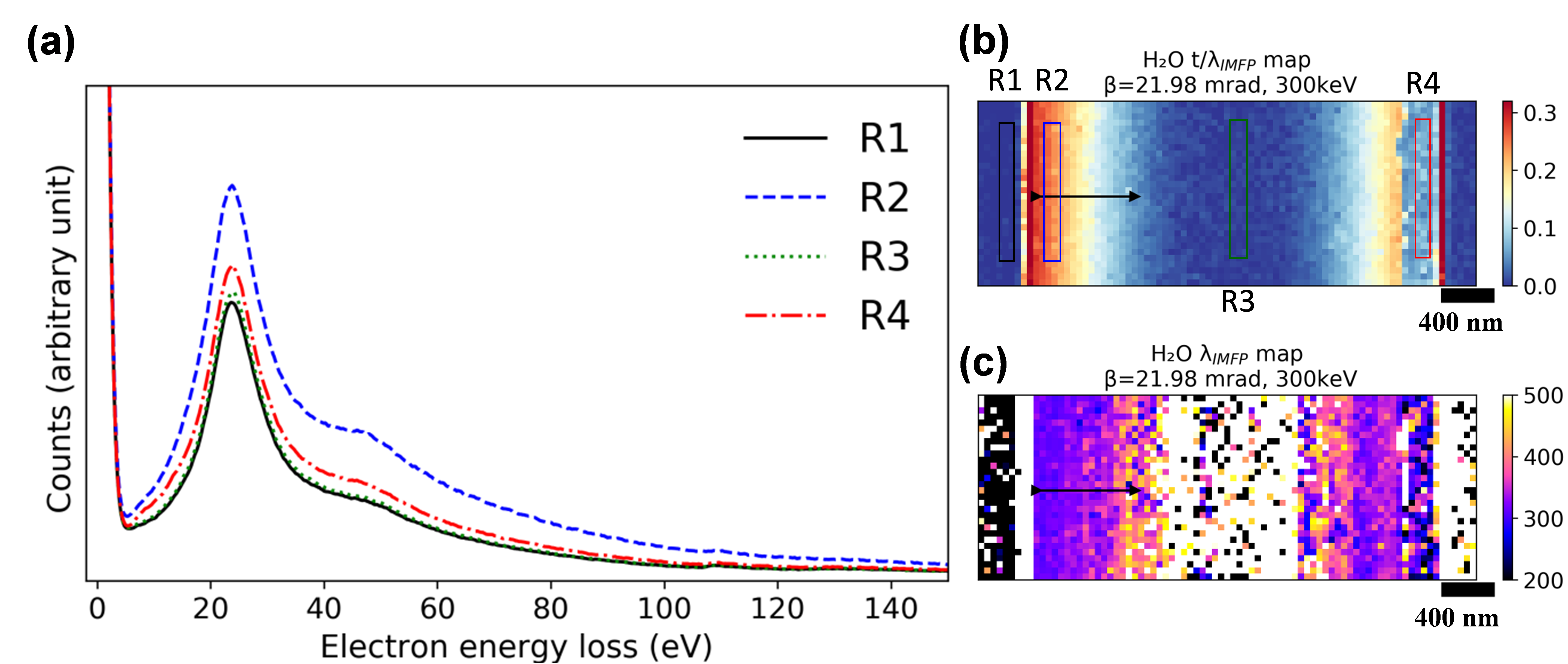
In general, knowledge of the water thickness is needed for reliable interpretation and modelling of many analytical studies in LPTEM. Having a precise measure of this parameter is particularly essential when using thin liquid layers, which is essential for achieving ultra-high spatial resolutions, or phase imaging [13]. The electron energy-loss spectroscopy (EELS) log-ratio method is often applied in TEM to estimate the sample thickness relative to the inelastic mean free path (lIMFP) [14,15]. However, lIMFP itself is dependent on the specific sample material, the electron energy, and the angular conditions and electron optics of the microscope electron optics. The electron scattering lIMFP of water was measured using the nanochannel liquid cell, as shown in Figure 2. The results are compared to previous experimental studies on water and ice, and two theoretical models [14-16]. We observe good agreement with the studies conducted on ice [17] but find that the widely accepted theoretical models significantly underestimate lIMFP of water. Using an adjusted average energy-loss term, Em,water, we find far better agreement between model and observations. The results are highly valuable, as a comprehensive knowledge of the lIMFP of water (or ice) under different electron optics conditions ensures reliable interpretation and quantification of observations in LPTEM and many cryo-TEM studies.
Figure 2. STEM-EELS measurement of electron inelastic mean free path in liquid water in a nanochannel liquid cell. (a) Summed EELS spectra from the regions indicated in Figure b. The signals are normalized to the maximum zero-loss peak intensity. R1: two bonded silicon nitride membranes; R2: two suspended silicon nitride membranes with liquid water in between; R3: two collapsed silicon nitride membranes assuming no liquid or ultra-thin water in between; R4: two suspended silicon nitride membranes with radiolysis gas and thin water layers on both membranes. (b) An example of the t/ λIMFP map of liquid water after subtracting the silicon nitride contribution; (c) the λIMFP map of liquid water.
Acknowledgment
We acknowledge financial support from the Danish Research Council for Technology and Production Case No. 12-126194. This work was supported in part by the Advanced Materials for Energy-Water Systems (AMEWS) Center, an Energy Frontier Research Center funded by the U.S. Department of Energy, Office of Science, Basic Energy Sciences. This work was supported by the U.S. Department of Energy, Office of Science, Office of Basic Energy Sciences, Division of Chemical Sciences, Geosciences & Biosciences. PNNL is operated by Battelle Memorial Institute for the U.S. Department of Energy under Contract No. DE-AC05-76RL01830.
corresponding authors
- References
[1] F. M. Ross, Science 350 (2015).
[2] Liquid Cell Electron Microscopy (Cambridge University Press, Cambridge, 2016), Advances in Microscopy and Microanalysis.
[3] M. N. Yesibolati, S. Laganà, H. Sun, M. Beleggia, S. M. Kathmann, T. Kasama, and K. Mølhave, Phys. Rev. Lett. 124, 065502 (2020).
[4] S. Lagana, E. K. Mikkelsen, R. Marie, O. Hansen, and K. Molhave, Microelectron. Eng. 176, 71 (2017).
[5] E. Völkl, L. F. Allard, and D. C. Joy, Introduction to Electron Holography (Kluwer Academic/Plenum Publishers, New York, 1999).
[6] S. M. Kathmann, I. F. W. Kuo, C. J. Mundy, and G. K. Schenter, The Journal of Physical Chemistry B 115, 4369 (2011).
[7] K. Leung, The Journal of Physical Chemistry Letters 1, 496 (2010).
[8] R. C. Remsing, M. D. Baer, G. K. Schenter, C. J. Mundy, and J. D. Weeks, J Phys Chem Lett 5, 2767 (2014).
[9] B. Sellner and S. M. Kathmann, J. Chem. Phys. 141, 18C534 (2014).
[10] T. A. Pham, C. Zhang, E. Schwegler, and G. Galli, Phys Rev B 89 (2014).
[11] A. Harsher and H. Lichte, Inelastic mean free path and mean inner potential of carbon foil and vitrified ice measured with electron holography (Iop Publishing Ltd, Bristol, 1998), Electron Microscopy 1998, Vol 1: General Interest and Instrumentation.
[12] T. Prozorov, T. P. Almeida, A. Kovács, and R. E. Dunin-Borkowski, J. R. Soc. Interface 14 (2017).
[13] N. de Jonge, Ultramicroscopy 187, 113 (2018).
[14] T. Malis, S. C. Cheng, and R. F. Egerton, J. Electron. Micr. Tech. 8, 193 (1988).
[15] R. F. Egerton and S. C. Cheng, Ultramicroscopy 21, 231 (1987).
[16] K. Iakoubovskii, K. Mitsuishi, Y. Nakayama, and K. Furuya, Microsc Res Techniq 71, 626 (2008).
[17] R. F. Egerton, in Proc. 50th Annual EMSA Meeting, edited by J. B. a. J. A. S. ed. by G.W. Bailey (San Francisco Press, San Francisco, 1992), pp. pp. 1264.