Probing unusual structural inhomogeneities in La0.7Sr0.3MnO3 thin films by STEM imaging
- Abstract number
- 834
- Event
- Virtual Early Career European Microscopy Congress 2020
- Presentation Form
- Submitted Poster
- DOI
- 10.22443/rms.emc2020.834
- Corresponding Email
- [email protected]
- Session
- PSA.9 - Magnetic and Spintronic Materials
- Authors
- DR. Piu Rajak (1), DR. Daniel Knez (1), DR. Sandeep Kumar Chaluvedi (1, 3), DR. Pasquale Orgiani (1, 4), DR. Paolo Perna (2), DR. Laurence Mechin (3), DR. Regina Ciancio (1)
- Affiliations
-
1. CNR-IOM TASC National Laboratory, Area Science Park- Basovizza
2. IMDEA-Nanociencia, Campus de Cantoblanco
3. Normandie Univ, UNICAEN, ENSICAEN, CNRS, GREYC, 14000
4. CNR-SPIN, UOS Salerno, 84084 Fisciano (SA)
- Keywords
EDS, HAADF STEM imaging, La0.7Sr0.3MnO3 Thin film, SAED
- Abstract text
Manganites with composition La0.7Sr0.3MnO3 (LSMO) are half-metallic room temperature ferromagnets and are considered as ideal candidates for (oxide) spintronic applications. Bulk LSMO possesses rhombohedral symmetry with space group and a-a-a- Glazer notation, revealing equal and out-of-plane BO6 octahedral tilting in all 3 directions. In thin-film form, the properties are very sensitive to interfacial strain states, octahedral coupling, etc. The ability to tune the magnetic anisotropy of LSMO thin films allows to control the magneto-transport response thus enabling the development of devices with targeted properties [1-7]. Very recently, it has been shown that the magnetic anisotropy can change from uniaxial to biaxial to weak by changing the film thickness from 12 to 25 to 50 nm, respectively [8].
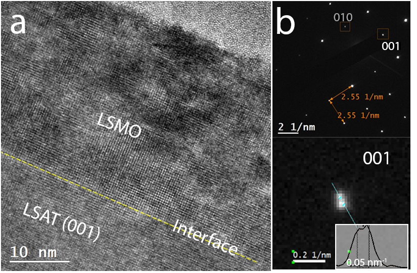
Here, we investigate the nanostructural properties of compressively strained epitaxial LSMO (apc=0.3876 nm) thin films of thickness 25 nm, grown by Pulsed Laser Deposition (PLD) on (LaAlO3)0.3-(Sr2AlTaO6)0.7 (LSAT) (apc= 0.387 nm) substrates in (001) orientation. Phase contrast imaging and Selected Area Electron Diffraction (SAED) have been performed to explore the film/substrate nanostructure. Figure 1a shows a representative high-resolution transmission electron microscopy (HRTEM) bright field micrograph of the film/substrate cross-section, while Figure 1b provides a corresponding selected area electron diffraction (SAED) pattern. SAED highlights the extremely good crystallographic matching between film and substrate. Interestingly, satellite spots can also be identified in the pattern in the direction parallel to the film/substrate interface (see magnified image of the (001) reflection).
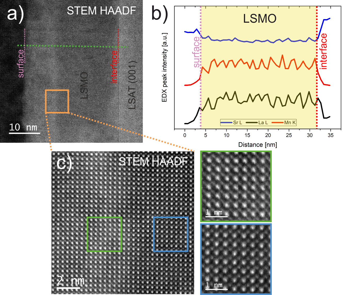
These findings suggest the possible existence of lattice distortions within the film, which we explored more carefully by high angle annular dark field (HAADF) scanning transmission electron microscopy (STEM) using a Cs corrected FEI Titan 60-300 microscope at the Institute for Electron Microscopy and Nanoanalysis (FELMI) at the Graz University of Technology, within the framework of the ESTEEM 3 programme. In Figure 2a representative STEM HAADF image of a cross sectional region of the specimen is shown. From this image, we can clearly identify the substrate on the right side and the LSMO film region on the left side. The film/substrate interface is atomically straight and sharp. Note that intensity variations can be seen within the film region, dividing the film into a diffuse darker contrast slab closer to the interface and a brighter one closer to the film surface.
Energy Dispersive X-ray Spectroscopy (EDS) has been performed to ascertain possible chemical differences throughout the film. In Figure 2b EDS line scan profiles of La, Sr and Mn taken along the green dashed line are shown, revealing no detectable changes in chemical composition within the film region or sign of interdiffusion between the substrate and the film. Based also on the information coming from phase contrast imaging and SAED, intensity variations detected by HAADF-STEM can be attributed to structural distortions occurring within the film region. This is confirmed by closer HAADF-STEM investigation performed at the region across the two slabs of the film (see dash edged orange box in Figure 2c). The regions marked in the green box and blue box (Figure 2c) show notable differences in intensity and structural orientation. Our results provide strong evidence on the existence of a structural inhomogeneity and local lattice distortions within the LSMO films which may affect their magnetic properties [9,10].
Figure 1: (a) TEM bright field image showing the LSMO film on LSAT substrate. (b) Selected area electron diffraction of film and substrate with orientation corresponding to (a). The magnified region around the (0-10) spot exhibits satellite reflections, further illustrated in the corresponding intensity profile in the inset.
Figure 2: (a) Cross-sectional STEM HAADF image showing film and substrate. (b) Result of an EDS line scan over the film region indicated by a green line in (a). (c) Magnified STEM HAADF image of the interfacial area between the ordered and disordered regions of the film. STEM HAADF images marked with the green and blue boxes are showing the change in intensity within those regions.
- References
[1] D. Kan et al., Nat. Mater., 15, 4 (2016), 432–437.
[2] Z. Liao et al., Nat. Mater., 15, 4 (2016), 425–431.
[3] J. Gázquez et al., Mater. Sci. Semicond. Process., (2017), 65,49–63.
[4] F. Y. Bruno et al., Nat. Commun., (2015). 6.
[5] F. Y. Bruno et al., Phys. Rev. Lett., (2011), 106, 14, 8–11.
[6] M. A. Roldan et al., Microsc. Microanal., (2014) 20, 6, 1791–1797.
[7] G. Sanchez-Santolino et al., Nat. Nanotechnol., (2017), 12, 7, 655–662.
[8] S. K. Chaluvadi, “Influence of the epitaxial strain on magnetic anisotropy in LSMO thin films for spintronics applications,” Electronics. Normandie Université, 2017. English. NNT : 2017NORMC248 . tel-01717569 HAL.
[9] This project has received funding from the European Union’s Horizon 2020 research and innovation programme under grant agreement No 823717 – ESTEEM3.
[10] E. Cociancich is gratefully acknowledged for the assistance in the TEM specimen preparation.