Visualization of thermal conduction in carbon nanotubes by in-situ transmission electron microscopy
- Abstract number
- 947
- Event
- European Microscopy Congress 2020
- DOI
- 10.22443/rms.emc2020.947
- Corresponding Email
- [email protected]
- Session
- PST.6 - In-situ and in-operando microscopy
- Authors
- Seiya Takimoto (1), Kaori Hirahara (1)
- Affiliations
-
1. Osaka University
- Keywords
Carbon nanotubes
Temperature distribution
In-situ TEM
- Abstract text
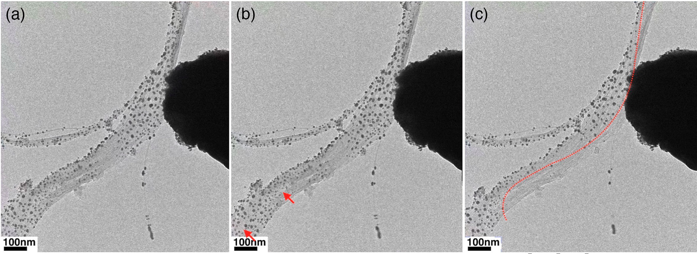
Flexible films of carbon nanotubes (CNTs) have attracted attention as potential high-performance thermoelectric materials for the efficient conversion of waste heat into electrical power [1]. Recently, it has been reported that control of the geometrical arrangement of CNTs is a key to enhancing the power factor of CNT films [2]. Experimental measurements of aligned CNT films have revealed that the electrical conductivity along the CNT alignment axis is several times greater than that along the perpendicular (cross-CNT) axis, and that the Seebeck coefficient is fully isotropic [2]. However, it is still unclear as to how heat is conducted across various types of interfaces, for example between neighboring CNTs in bundles of CNTs, at junctions of bundled CNTs, etc., in aligned CNT films. We have endeavored to visualize the temperature distribution in a partially-heated bundle of CNTs by using gold nanoparticles as thermometers and imaging in a transmission electron microscope (TEM, JEOL JEM-2500SE) operated at an acceleration voltage of 90 kV. The CNTs used in this study were single-walled CNTs (Arc-SO, Meijo Nanocarbon Co.) with averaged diameter of ~1.4 nm. Prior to the experiment, we confirmed that gold nanoparticles of 10 – 20 nm in diameter almost disappear when heated to 800 °C using a heating TEM-specimen holder. This indicates that monitoring the areas where gold nanoparticles have sublimated, over time, yields a visualization of the thermal pathways for the CNT regions reaching > 800 °C. For the experiment, gold nanoparticle-decorated bundles of CNTs were mounted on the specimen stage of a Nanofactory TEM–STM holder, and a platinum electrode probe tip was contacted to a selected bundle in preparation for the Joule heating. Figure 1(a) shows a TEM image of a CNT bundle with a ~140 nm width and more than a 2 µm length. Both ends of this bundle were affixed to the specimen stage, with several other bundles forming junction structures. The probe tip was positioned to make contact to side walls of several CNTs of the bundle. This CNT bundle was then heated by applying a voltage between the stage and the probe. The voltage was increased by 10 mV/s. First, the two gold particles indicated by arrows sublimated/coalesced at 2.5 V (Fig. 1(b)). Current then sharply increased at 2.56 V due to improvement in the electrical contact at the CNT-probe interface, and gold particles sublimated from a rather wide area along the axial direction of the CNT; the area sublimated is below the dotted line in the image (Fig. 1(c)).
The temperature distribution in this geometry is understood to be described by the summation of three factors: Joule heating at the CNT-probe contact, variation of the degree of Joule heating in individual CNTs, and anisotropic heat conduction in CNTs along their axes, and along the perpendicular axis. One heat source may be dominant at an early stage of heating at a low voltage, but we note that the contact area was not heated sufficiently to melt/sublimate any of the gold nanoparticles. Instead, some specific particles in particular locations may melt due to axial heat conduction along one or several CNTs directly in contact with the probe. After improving the electrical contact, Joule heating of the CNTs becomes the dominant heat source with the drastically increasing current. Here it is noted that the expansion of the high-temperature area in the perpendicular direction, 80 nm width at its maximum, is not consistent with the variation of the amount of Joule heat generation in individual CNTs as estimated by considering anisotropic electron conductivity along the axial and perpendicular directions of the aligned CNTs; namely we have visualized the degree of heat conduction in the CNT-perpendicular direction.
This work was supported by JST CREST Grant Number JPMJCR1715, Japan.
Figure 1. A gold-nanoparticle-decorated-bundle of single walled carbon nanotubes connected to a platinum probe tip. (a) initial. (b) At 2.50V, two nanoparticles disappeared (red arrows). (c) At 2.56 V, gold nanoparticles sublimated at a region below the red dotted line, where the width in axial direction was more than 800 nm and that in perpendicular direction was 80 nm in maximum.
- References
[1] Y. Ichinose et al. Nano Lett. 19 (2019), pp. 7370-7376.
[2] K. Fukuhara et al. App. Phys. Lett. 113 (2018), p. 243105.
[3] This work was supported by JST CREST Grant Number JPMJCR1715, Japan.